
TM 5-3805-294-23-1
0003
HYDRAULIC SYSTEM - Continued
94
95
99
105
103
104
102
101
100
98
99
98
97
96
HYEX01690
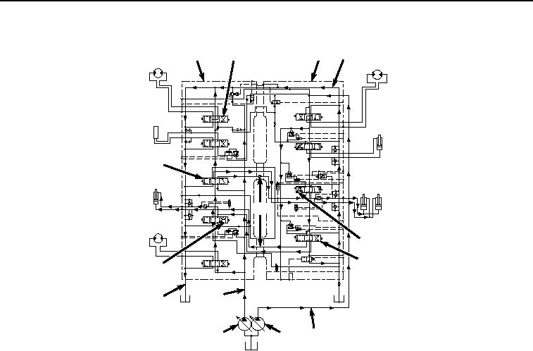
Figure 15. Neutral and Power Passages Operation.
All valves are accessible from the outside of the control valve by removing a plug, cover, or the pilot caps. The
solenoid valve manifold, which contains the power dig, arm regenerative, swing priority, and travel speed solenoid
valves is also located on the right control valve.
Supply oil from pump 1 (Figure 15, Item 96) flows to the right control valve (Figure 15, Item 95). Supply oil from pump
2 (Figure 15, Item 97) flows to the left control valve (Figure 15, Item 94). When all functions are in neutral, supply
oil flows through the neutral and power passages (Figure 15, Item 98) for each valve spool section and then into the
return passage (Figure 15, Item 99). Neutral and power passages in the left and right control valves are used to
route supply oil for the combined operation of functions. Arm 1 and 2 spools (Figure 15, Items 100 and 101), and
the boom 1 and 2 spools (Figure 15, Items 102 and 103), are connected by combiner passages (Figure 15, Item
104) so supply oil from both pump 1 and pump 2 flows to the cylinders during a single operation. Supply oil from
pump 2 can be combined with supply oil from pump 1 by the auxiliary combiner power passage to supply the auxiliary
spool (Figure 15, Item 105).
Pilot Signal Manifold
The pilot signal manifold is in the pilot system between the pilot control valves and the main control valve and
regulators. The manifold receives a pilot signal from the pilot control valves and sends the signal on multiple paths.
One path is used to shift the spools in the control valve and the other sends a signal to the regulators through pump
2 flow rate pilot valve and pump 1 flow rate pilot valve. This is done simultaneously so there is little lag between
operation of the pilot control valves, pump stroke, and function movement. The manifold also houses additional pilot
valves that provide pilot oil for various other functions.