
TM 5-3805-294-23-1
0003
HYDRAULIC SYSTEM - Continued
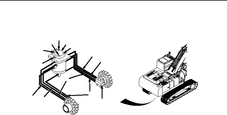
during swing operation. Oil flows into and through the spindle to passages in the housing, and then out of the housing
to the travel motors. Sealing rings stop oil from leaking between the spindle and housing into adjacent passages.
86
85
84
85
86
85
86
85
87
85
85
86
88
HYEX01688
Figure 13.
Center Joint Operation.
Cylinders
The boom cylinders are located on each side of the boom and are attached to the main frame. When activated, they
raise and lower the boom.
The arm cylinder is located on the top of the boom and the arm. When activated, this cylinder moves the arm in and
out.
The thumb cylinder is located on the bottom of the arm and connects to the thumb. When activated, this cylinder
extends to clamp with the thumb or retracts to unclamp the thumb. The thumb cylinder can be shutdown to provide
hydraulic power to operate the crusher, breaker, compactor and deep dig arm.
The bucket cylinder is located on the top of the arm and connects to the quick latch. When activated, this cylinder
extends to curl the bucket/attachment or retracts to dump the bucket/attachment.
Reduced Leakage Valve
NOTE
The operational principles of the boom and arm reduced leakage valves are identical.
Therefore, boom reduced leakage valve operation is used as an example.
Reduced leakage valves are used in the boom head end circuit. The function of a reduced leakage valve is to reduce
cylinder drift by stopping leakage from the cylinder back through the control valve.
When the control valve is in neutral, the oil pressure generated by the load on the cylinders is applied to the spring
end of boom reduced leakage valve check valve (Figure 14, Item 89) through the boom reduced leakage valve switch
valve (Figure 14, Item 90). The check valve is held closed against the seat in housing trapping the oil from the
cylinders at the work port.