
TM 5-3805-294-23-1
0003
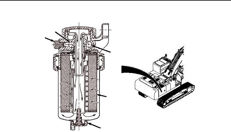
FUEL SYSTEM - Continued
156
158
154
1
155
157
HYEX01698
Figure 23. Final Fuel Filter Operation.
Since water and contaminants settle at the bottom of the sediment bowl, a drain plug (Figure 23, Item 157) is
provided.
Air in the system can be expelled through the air vent when bleed screw (Figure 23, Item 158) is loosened.
High-Pressure Side and Electronic Control
Filtered fuel enters the high-pressure pump through the fuel inlet (Figure 24, Item 159). Once fuel passes through
the inlet, it goes through a fuel inlet filter and continues through an internal transfer pump. Fuel is then routed either
to lubricate the pump crankcase or to the suction control valve (Figure 24, Item 160). The suction control valve is a
solenoid valve controlled by the ECU. The ECU supplies the suction control valve current when it is time to release
fuel to the high-pressure common rail. There is one chamber on the top of the pump and another chamber on the
bottom of the pump. Fuel in each chamber is pressurized when the pump camshaft rotates. Excess fuel leaves the
pump through the overflow orifice (Figure 24, Item 161), so it can return to the fuel tank.