
TM 5-3805-294-23-1
0003
FUEL SYSTEM - Continued
Injectors
The electronic injectors are located in the engine's cylinder head and are electronically controlled by the ECU. The
amount of fuel delivered to the cylinder is controlled by the length of time current is supplied to the two-way
electromagnetic valve (TMV) (Figure 26, Item 168) on each electronic injector. The ECU sends signals in specific
sequence to each electronic injector. This controls the volume of fuel, and the timing of delivery for each electronic
injector.
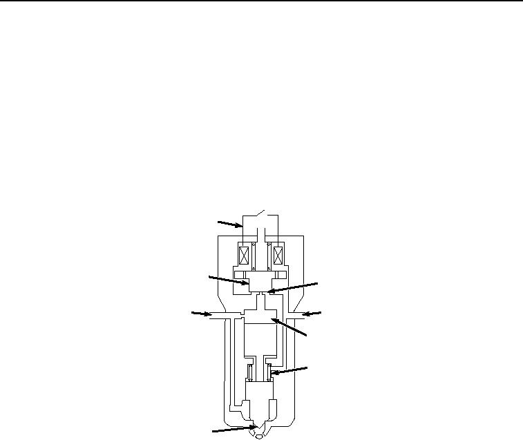
Fuel from the high-pressure common rail enters the electronic injectors at fuel inlet (Figure 26, Item 169). When no
current is supplied to the electromagnetic valve (Figure 26, Item 168), valve spring (Figure 26, Item 170) and the
hydraulic pressure of the fuel in control chamber (Figure 26, Item 171) cause the hydraulic piston to push the needle
down and close nozzle (Figure 26, Item 172). This holds the high-pressure fuel from the common rail inside the
nozzle until injection.
168
173
174
169
175
171
170
172
HYEX01702
Figure 26.
No/Ending Injection.
Injection begins when current is supplied from the ECU to the electromagnetic valve (Figure 26, Item 168). The
electromagnetic force pulls the solenoid valve (Figure 26, Item 173) up, causing the orifice seat (Figure 26, Item
174) to open. The fuel in the control chamber (Figure 26, Item 171) flows out of the injector to the fuel leak-off line
(Figure 26, Item 175). Fuel is then routed back to the fuel tank. As the fuel exits the injector, the force is removed
from the hydraulic piston, the nozzle needle lifts, allowing fuel through the nozzle (Figure 26, Item 172) to start the
injection process.
Injection ends when the current is removed from the electromagnetic valve (Figure 26, Item 168). The solenoid valve
(Figure 26, Item 173) closes, causing fuel to fill the control chamber (Figure 26, Item 171). The valve spring and the
hydraulic force from the fuel in the control chamber cause the hydraulic piston to push the needle down and close
the nozzle (Figure 26, Item 172). At this time the injection is complete.
COOLING SYSTEM
Radiator
The radiator is next to the fan and hydraulic oil cooler. Coolant circulates through the radiator to be cooled after
leaving the cylinder block.