
TM 5-3805-294-23-1
0003
FUEL SYSTEM - Continued
161
159
160
162
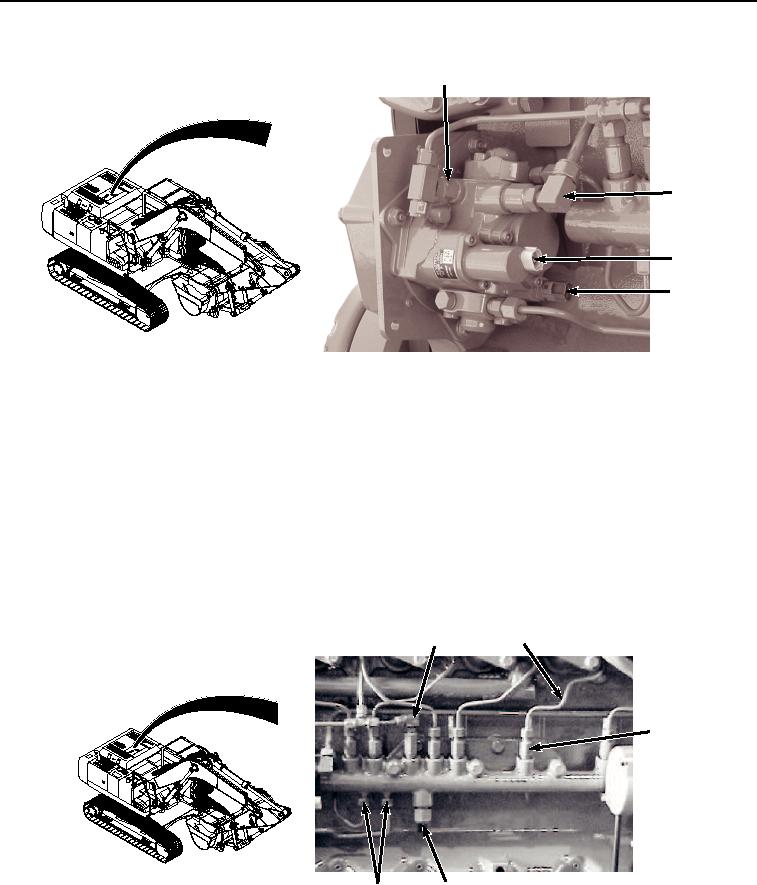
HYEX01699
Figure 24.
High-Pressure Fuel Pump Operation.
A fuel temperature sensor (Figure 24, Item 162) is included on the pump to measure the fuel temperature in the
pump housing.
High-pressure fuel is delivered to the high-pressure common rail through two high-pressure pump delivery lines
(Figure 25, Item 163). The high-pressure common rail delivery lines (Figure 25, Item 164) transport fuel to the
electronic injectors. The fuel rail pressure sensor (Figure 25, Item 165) detects fuel pressure inside the rail. The ECU
uses this sensor to monitor fuel pressure to determine the timing of the suction control valve on the high-pressure
fuel pump. If an abnormally high-pressure is generated within the high-pressure common rail, the safety relief valve
(Figure 25, Item 166) opens to release the excess pressure and drain fuel back to the tank. The flow restrictors
(Figure 25, Item 167) are used to control the maximum fuel flow to the electronic injectors and prevent damage if
the electronic injectors should fail, or if a high-pressure leak develops, by shutting off fuel flow to the failed electronic
injectors.
166
164
167
165
163
HYEX01700
Figure 25.
High-Pressure Common Rail Operation.