
TM 5-3805-294-23-1
0003
HYEX THEORY OF OPERATION - Continued
Engine Operation - Continued
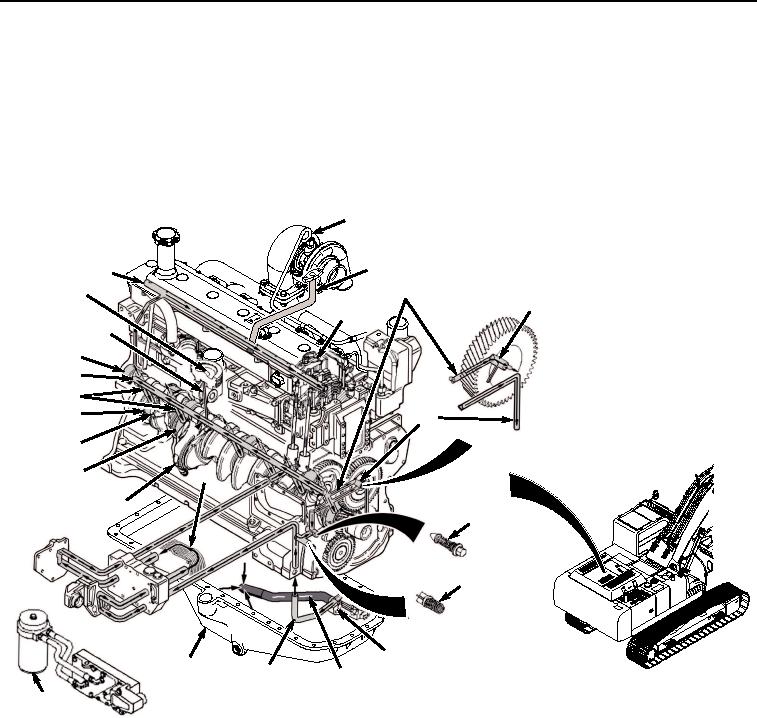
Lubrication
The engine lubrication system consists of a positive displacement gear-driven oil pump (Figure 5, Item 31), full-flow
oil filter (Figure 5, Item 32), oil cooler (Figure 5, Item 33), oil pressure regulating valve (Figure 5, Item 34), and an
oil bypass valve (Figure 5, Item 35).
52
53
48
46
50
51
49
47
41
39
40
42
43
45
33
53
44
34
35
31
36
38
37
32
HYEX01679
Figure 5.
Engine Lubrication System.
The oil pump pulls oil from the oil pan sump (Figure 5, Item 36) through a strainer and suction line (Figure 5, Item
37). The pump forces oil through the outlet tube (Figure 5, Item 38) into a vertical drilling in the cylinder block, and
up to the oil cooler and remote mounted filter (Figure 5, Item 32). After flowing through the cooler and filter, oil flows
into the oil gallery (Figure 5, Item 39).
The main oil gallery runs the length of the cylinder block and delivers oil to oil passages (Figure 5, Item 40) that feed
the camshaft bushings (Figure 5, Item 41) and main bearing bushings (Figure 5, Item 42). The cross-drillings (Figure
5, Item 43) intersect with those same oil passages.
From the main bearings, oil flows to the connecting rod bearings (Figure 5, Item 44) through drilled cross passages
(Figure 5, Item 45) in the crankshaft between the main journals and connecting rod journals. Oil from the main bearing
also supplies oil to the piston cooling orifices.