
TM 5-3805-294-23-4
0499
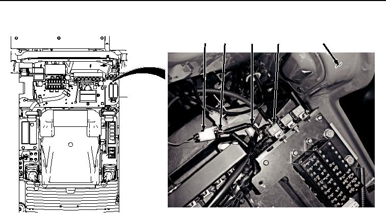
CONTROL WIRING HARNESS INSTALLATION - Continued
4
3
8
5, 6, 7
9
HYEX03154
Figure 7.
Connect Control Wiring Harness To Power Delivery Wiring Harness.
2.
Connect control wiring harness connector (Figure 7, Item 7) to relay (Figure 7, Item 5).
3.
Install relay (Figure 7, Item 5) to bracket (Figure 7, Item 6).
4.
Connect control wiring harness connector (Figure 7, Item 3) to power delivery wiring harness connector (Figure
7, Item 4).
5.
Connect auxiliary fuse box wiring harness W13 connector X55 (Figure 8, Item 1) to control wiring harness
connector CAB LAMP FRONT (Figure 8, Item 2).