
TM 5-3805-294-23-4
0510
INSTALLATION - Continued
27
28
31
29
32
30
34
5
33
35
36
6
HYEX03194
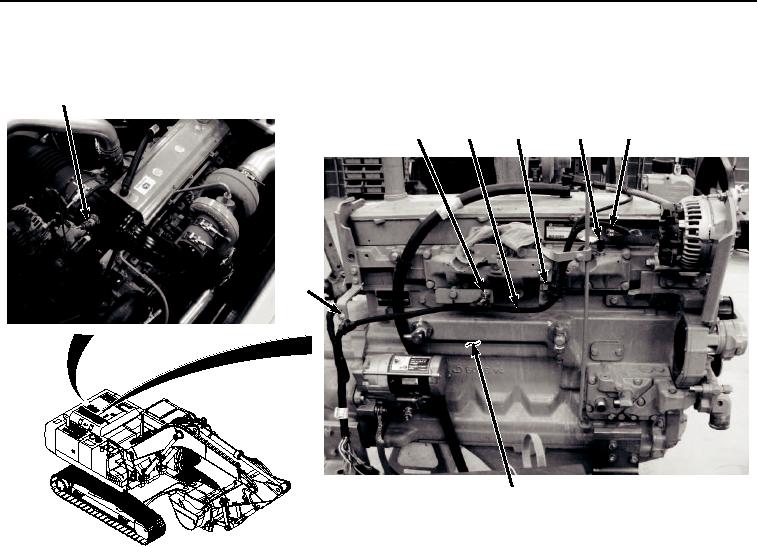
Figure 8. Engine Right Side Wiring Harness Installation.
8.
Install bolt and clamp assembly (Figure 8, Item 34) and engine wiring harness (Figure 8, Item 5) to engine
(Figure 8, Item 6).
9.
Install bolt and clamp assembly (Figure 8, Item 33) and engine wiring harness (Figure 8, Item 5) to engine
(Figure 8, Item 6).
10.
Connect engine wiring harness connector T02 (Figure 8, Item 31) to manifold air temperature sensor (Figure
8, Item 32).
11.
Connect engine wiring harness connector C01 (Figure 8, Item 29) to fuel injector (Figure 8, Item 30).
12.
Connect engine wiring harness connector T06 (Figure 8, Item 27) to compressor inlet temperature sensor
(Figure 8, Item 28).
13.
Install engine wiring harness (Figure 9, Item 5), and bracket (Figure 9, Item 25) to engine (Figure 9, Item 6)
with two spacers (Figure 9, Item 26), and screws (Figure 9, Item 24).