
TM 5-3805-294-23-4
0516
REMOVAL - Continued
9
1
14
3
13
14
12
11
12
13
11
9
10
7
8
5
7
6
HYEX02483
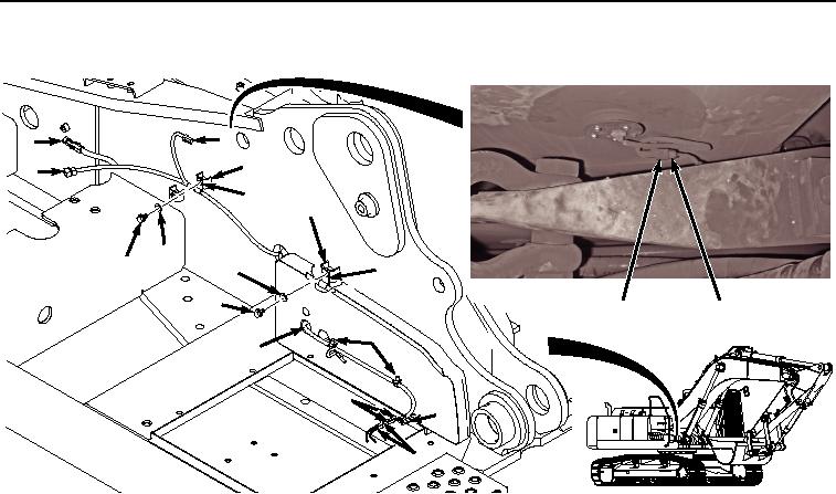
Figure 2. Remove Wiring Harness From E1, X67, and B18.
4.
Release three clips (Figure 2, Item 7) from wiring harness (Figure 2, Item 8).
5.
Disconnect wiring harness connector B18 (Figure 2, Item 9) from fuel level sensor (Figure 2, Item 10).
6.
Remove two bolts (Figure 2, Item 11), washers (Figure 2, Item 12), clamps (Figure 2, Item 13), and wiring
harness (Figure 2, Item 8) from frame (Figure 2, Item 14).
7.
Pull wiring harness (Figure 3, Item 8) through frame (Figure 3, Item 14) to center area between swing motor
and boom.