
TM 5-3805-294-23-4
0516
REMOVAL - Continued
25
24
23
19
18
22
17
B24
21
16
17
B23
15 18
19
14
8
20
HYEX02484
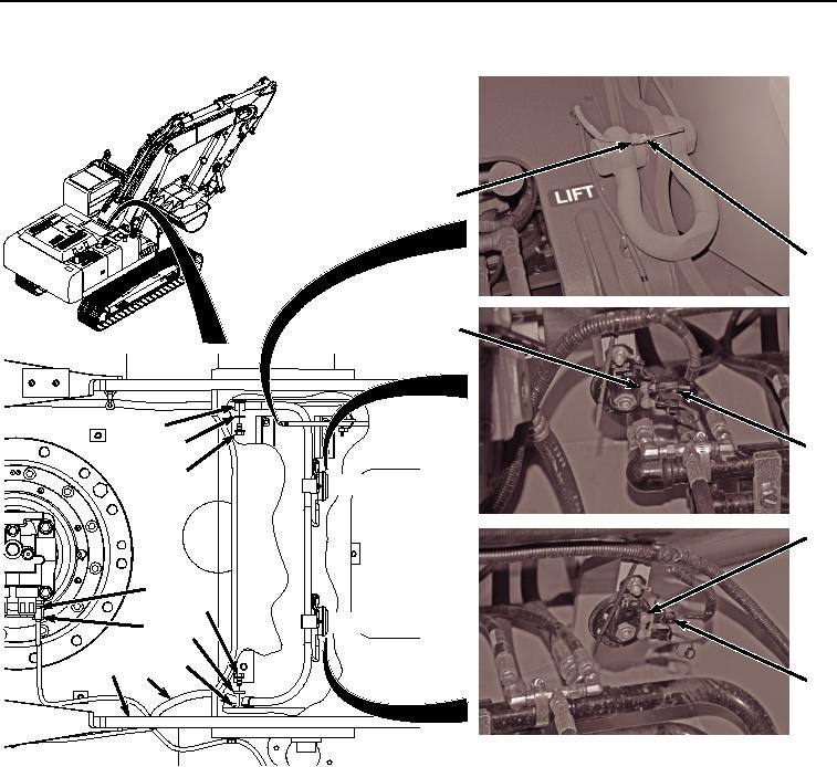
Figure 3.
Remove Wiring Harness From B32, B23, B24, and E2.
8.
Disconnect wiring harness connector B32 (Figure 3, Item 15) from front attachment pressure sensor (Figure
3, Item 16) on swing motor.
9.
Remove two screws (Figure 3, Item 17), washers (Figure 3, Item 18), clamps (Figure 3, Item 19), and wiring
harness (Figure 3, Item 8) from frame (Figure 3, Item 14).
10.
Disconnect wiring harness power connector B23 (Figure 3, Item 20) from high note horn (Figure 3, Item 21).
11.
Disconnect wiring harness power connector B24 (Figure 3, Item 22) from low note horn (Figure 3, Item 23).
12.
Disconnect wiring harness connector E2 (Figure 3, Item 24) from boom power wire harness (Figure 3, Item
25).
13.
Disconnect wiring harness connector B33 (Figure 4, Item 26) from swing pressure sensor (Figure 4, Item 27).