
TM 5-3805-294-23-4
0530
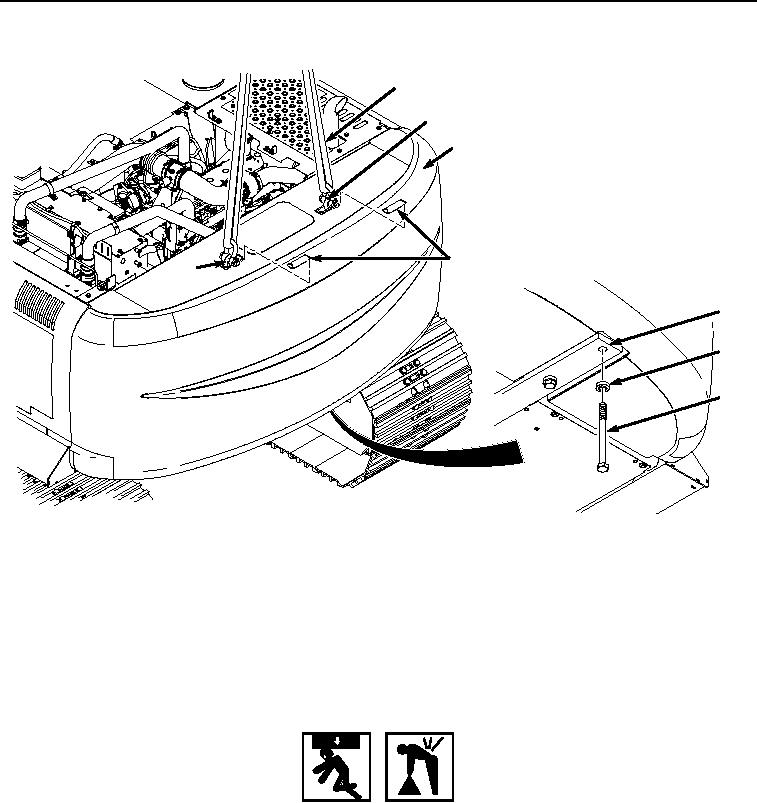
REMOVAL - Continued
10
11
9
8
11
14
13
12
HYEX02358
Figure 2. Counterweight Cap Removal.
5.
Attach a suitable lifting device (Figure 2, Item 10) to counterweight (Figure 2, Item 9) using two counterweight
lift eyes (Figure 2, Item 11).
6.
Place crowbar in between counter weight and frame to brace torque multiplier handle.
7.
Remove four bolts (Figure 2, Item 12) and washers (Figure 2, Item 13) from frame (Figure 2, Item 14) and
counterweight (Figure 2, Item 9).
WARNING
Counterweight weighs approximately 13,450 lb (6100 kg). Do not attempt to lift or move
counterweight without the aid of assistants and a suitable lifting device. Failure to comply
may result in injury or death to personnel.
8.
With the aid of two assistants and a suitable lifting device, remove counterweight (Figure 2, Item 9) from frame
(Figure 2, Item 14).
END OF TASK