
TM 5-3805-294-23-4
0540
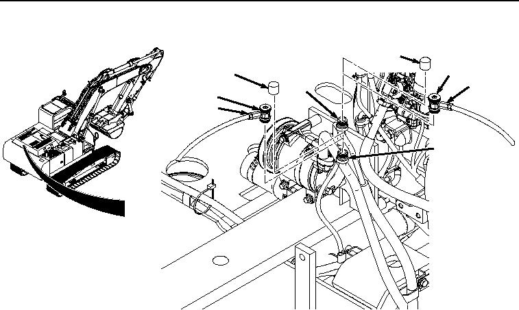
EVACUATION - Continued
1
8
3
5
2
7
6
4
HYEX01885
Figure 4.
Cap Removal for Evacuation.
2.
Remove low-pressure cap (Figure 4, Item 3) from service valve (Figure 4, Item 4).
3.
Connect high-pressure (red) hose (Figure 4, Item 5) to service valve (Figure 4, Item 2).
4.
Connect low-pressure (blue) hose (Figure 4, Item 6) to service valve (Figure 4, Item 4).
5.
Open low-pressure (blue) hose coupler (Figure 4, Item 7) by turning clockwise.
6.
Open high-pressure (red) hose coupler (Figure 4, Item 8) by turning clockwise.
7.
Using recovery machine (Figure 5, Item 9) operating instructions, evacuate air conditioning system until there
is a vacuum of 29 in hg (98 kPa) in the system.