
TM 5-3805-294-23-4
0540
EVACUATION
1
8
3
5
2
7
6
4
HYEX01885
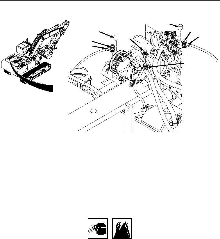
Figure 6.
Cap Installation After Evacuation.
11.
Close low-pressure (blue) hose coupler (Figure 6, Item 7) by turning counter-clockwise.
12.
Remove low-pressure (blue) hose (Figure 6, Item 6) from service valve (Figure 6, Item 4).
13.
Remove high-pressure (red) hose (Figure 6, Item 5) from service valve (Figure 6, Item 2).
14.
Install low-pressure cap (Figure 6, Item 3) to service valve (Figure 6, Item 4).
15.
Install high-pressure cap (Figure 6, Item 1) to service valve (Figure 6, Item 2).
END OF TASK
AIR CONDITIONER SYSTEM CHARGING
WARNING
Use care to prevent refrigerant from touching skin or eyes. Liquid refrigerant, when
exposed to air, quickly evaporates and will freeze skin or eye tissues. Failure to comply
may result in injury or death to personnel.
Do not attempt to apply compressed air to the internal components of refrigerant R-134a
air conditioning systems for pressure or leak test. Combustible mixtures of air and R-134a
may form resulting in a fire or explosion. Failure to comply may result in injury or death
to personnel.