
TM 5-3805-294-23-4
0557
REMOVAL - Continued
5.
Remove any pieces of broken glass or debris, and any remaining adhesive from door flange (Figure 2, Item
2).
END OF TASK
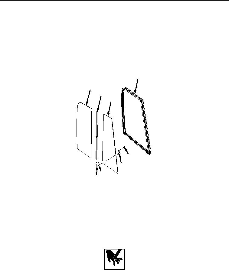
DISASSEMBLY
1.
Remove two screws (Figure 3, Item 5), latch assembly (Figure 3, Item 6), and spacer (Figure 3, Item 7) from
window (Figure 3, Item 8).
3
10
9
8
5
6
7
6
HYEX02645
Figure 3.
Window Frame Disassembly.
NOTE
Note position of glass during removal to ensure proper installation.
2.
Lift window frame (Figure 3, Item 3) slightly at top center and remove window (Figure 3, Item 8).
3.
Lift window frame (Figure 3, Item 3) slightly at top center and remove seal (Figure 3, Item 9).
4.
Lift window frame (Figure 3, Item 3) slightly at top center and remove window (Figure 3, Item 10).
WARNING
Replace broken window glass carefully. Wear a pair of heavy leather gloves or other suitable
hand protection. Support window glass during removal and installation, as required, so it does
not drop. Failure to comply may result in serious injury or death to personnel.