
TM 5-3805-294-23-4
0564
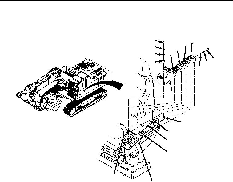
UPPER COVER REMOVAL - Continued
1.
Remove four screws (Figure 1, Item 1), lockwashers (Figure 1, Item 2), washers (Figure 1, Item 3), and spacers
(Figure 1, Item 4) from boot (Figure 1, Item 5) and cover (Figure 1, Item 6). Discard lockwashers.
1
18
16
2
14
12
3
7
4
8
9
6
17
15
13
11
5
10
HYEX00836
Figure 1.
Upper Cover Removal.
2.
Remove bolt (Figure 1, Item 7), lockwasher (Figure 1, Item 8), and washer (Figure 1, Item 9) from cover (Figure
1, Item 6). Discard lockwasher.
3.
Remove cover (Figure 1, Item 6) from left-hand console (Figure 1, Item 10).
4.
Disconnect wiring harness connector (Figure 1, Item 11) from travel alarm cancel switch (Figure 1, Item 12).
5.
Disconnect wiring harness connector (Figure 1, Item 13) from cab rear work lights switch (Figure 1, Item 14).
6.
Disconnect wiring harness connector (Figure 1, Item 15) from auxiliary control switch (Figure 1, Item 16).
7.
Disconnect wiring harness connector (Figure 1, Item 17) from reversing fan switch (Figure 1, Item 18).
END OF TASK
UPPER COVER DISASSEMBLY
1.
Remove four screws (Figure 2, Item 19) from case (Figure 2, Item 20).