
TM 5-3805-294-23-4
0564
UPPER COVER DISASSEMBLY - Continued
6
21
20
24
19
23
22
HYEX00897
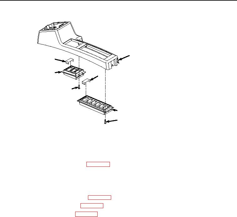
Figure 2.
Upper Cover Disassembly.
2.
Remove case (Figure 2, Item 20) from cover (Figure 2, Item 6).
3.
Remove two caps (Figure 2, Item 21) from case (Figure 2, Item 20).
4.
Remove travel alarm cancel switch. (WP 0617)
5.
Remove four screws (Figure 2, Item 22) from case (Figure 2, Item 23).
6.
Remove case (Figure 2, Item 23) from cover (Figure 2, Item 6).
7.
Remove four caps (Figure 2, Item 24) from case (Figure 2, Item 23).
8.
Remove cab rear work lights switch. (WP 0502)
9.
Remove auxiliary control switch. (WP 0491)
10.
Remove fan reversing switch. (WP 0523)
END OF TASK
SIDE COVERS REMOVAL
1.
Remove coolant heater display, if required. (Volume 3, WP 0463)
2.
Remove bolt (Figure 3, Item 25), lockwasher (Figure 3, Item 26), and washer (Figure 3, Item 27) from cover
(Figure 3, Item 28). Discard lockwasher.