
TM 5-3805-294-23-4
0564
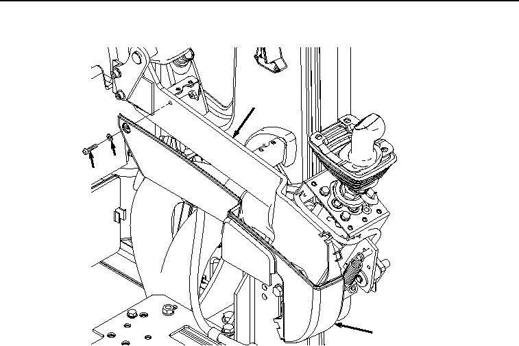
SIDE COVERS REMOVAL
10
39
38
32
HYEX01133
Figure 5.
Inner Side Cover Removal.
END OF TASK
SIDE COVERS INSTALLATION
1.
Install cover (Figure 6, Item 32) to left-hand console (Figure 6, Item 10) with screw (Figure 6, Item 38) and
washer (Figure 6, Item 39).