
TM 5-3805-294-23-4
0564
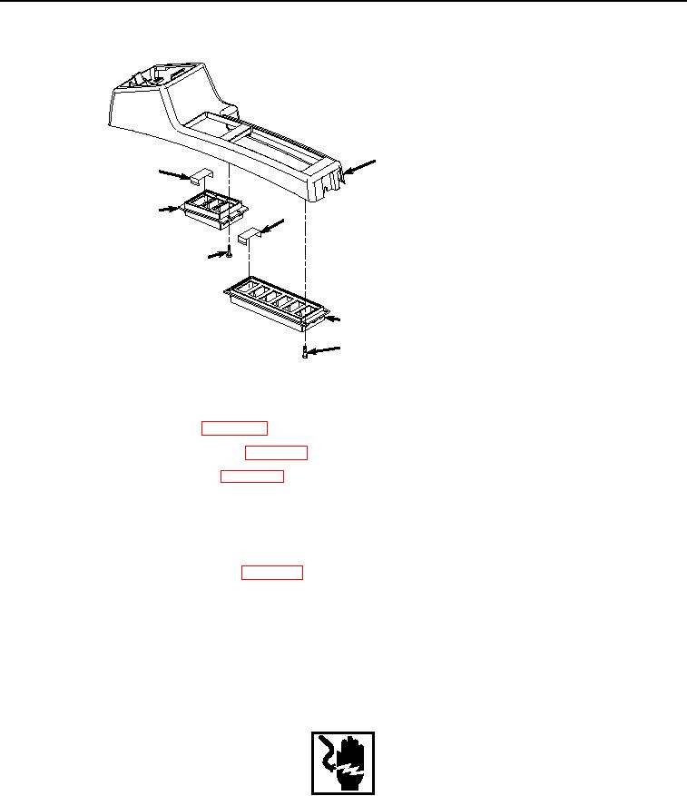
UPPER COVER ASSEMBLY - Continued
6
21
20
24
19
23
22
HYEX00897
Figure 9.
Upper Cover Assembly.
2.
Install fan reversing switch. (WP 0523)
3.
Install cab rear work lights switch. (WP 0502)
4.
Install auxiliary control switch. (WP 0491)
5.
Install case (Figure 9, Item 23) to cover (Figure 9, Item 6).
6.
Install four screws (Figure 9, Item 22) to case (Figure 9, Item 23).
7.
Install two caps (Figure 9, Item 21) to case (Figure 9, Item 20).
8.
Install travel alarm cancel switch. (WP 0617)
9.
Install case (Figure 9, Item 20) to cover (Figure 9, Item 6).
10.
Install four screws (Figure 9, Item 19) to case (Figure 9, Item 20).
END OF TASK
UPPER COVER INSTALLATION
WARNING
Ensure electrical power is off prior to working on all electrical connections. Prior to working
on or around vehicle, remove all jewelry, such as rings, ID tags, bracelets, etc. Jewelry, and
tools can catch on equipment, contact positive electrical circuits, and cause a direct short,
severe burns, or electrical shock. Failure to comply may result in injury or death to personnel.