
TM 5-3805-294-23-4
0564
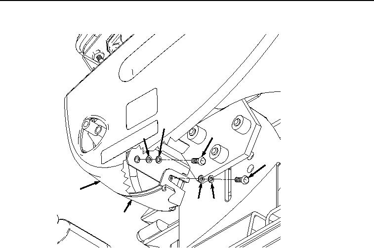
SIDE COVERS INSTALLATION - Continued
26
27
25
29
28
31
30
32
HYEX01131
Figure 8.
Side Covers Installation.
5.
Install bolt (Figure 8, Item 25), lockwasher (Figure 8, Item 26), and washer (Figure 8, Item 27) to cover (Figure
8, Item 28).
6.
Install coolant heater display, if required. (Volume 3, WP 0463)
END OF TASK
UPPER COVER ASSEMBLY
1.
Install four caps (Figure 9, Item 24) to case (Figure 9, Item 23).