
TM 5-3805-294-23-4
0564
SIDE COVERS REMOVAL - Continued
10
37
36
33
34
35
32
28
HYEX01132
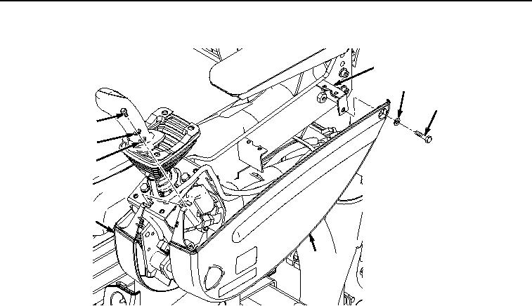
Figure 4.
Outer Side Cover Removal.
5.
Remove bolt (Figure 4, Item 36), washer (Figure 4, Item 37), and cover (Figure 4, Item 28) from left-hand
console (Figure 4, Item 10).
6.
Remove screw (Figure 5, Item 38), washer (Figure 5, Item 39), and cover (Figure 5, Item 32) from left-hand
console (Figure 5, Item 10).