
TM 5-3805-294-23-4
0564
SIDE COVERS INSTALLATION - Continued
10
39
38
32
HYEX01133
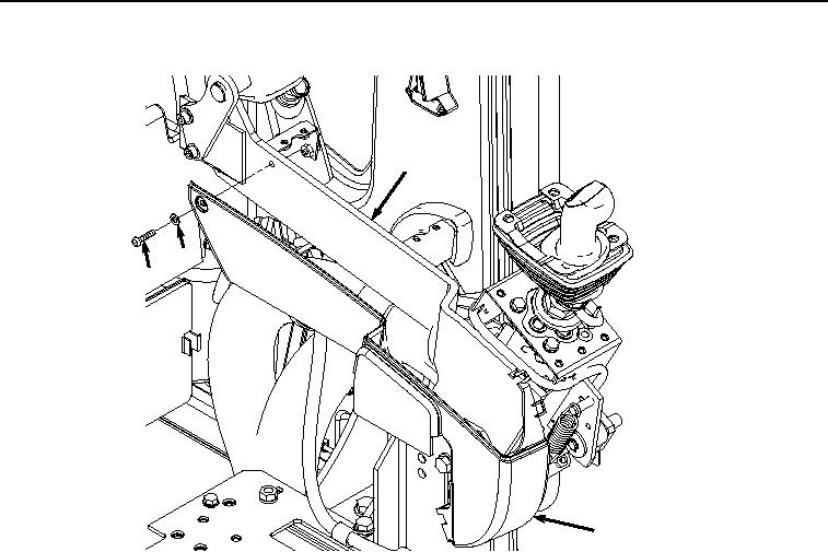
Figure 6.
Inner Side Cover Installation.
2.
Install cover (Figure 7, Item 28) to left-hand console (Figure 7, Item 10) with bolt (Figure 7, Item 36) and washer
(Figure 7, Item 37).