
TM 5-3805-294-23-4
0572
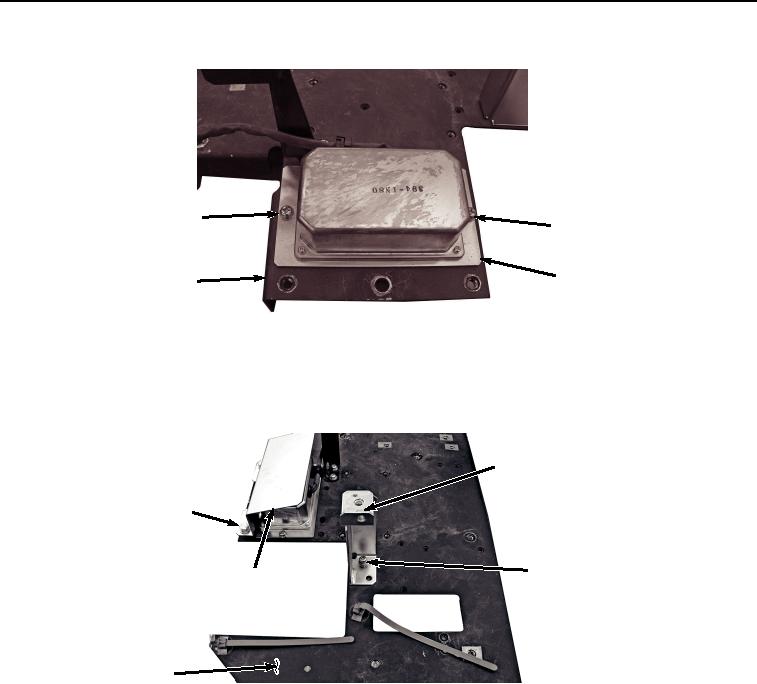
ASSEMBLY - Continued
69, 70, 71
69, 70, 71
72
20
HYEX02607
Figure 23. Power Converter Installation.
5.
Install power convertor cover (Figure 24, Item 68) to bracket (Figure 24, Item 20) with two bolts (Figure 24,
Item 66) and washers (Figure 24, Item 67).
65
66, 67
62, 63, 64
68
20
HYEX02606
Figure 24. Power Converter Cover Installation.
6.
Install bracket (Figure 24, Item 65) to bracket (Figure 24, Item 20) with two screws (Figure 24, Item 62),
lockwashers (Figure 24, Item 63), and washers (Figure 24, Item 64).
7.
Install information controller (Figure 25, Item 37) to bracket (Figure 25, Item 20) with three screws (Figure 25,
Item 59), lockwashers (Figure 25, Item 60), and washers (Figure 25, Item 61).