
TM 5-3805-294-23-4
0572
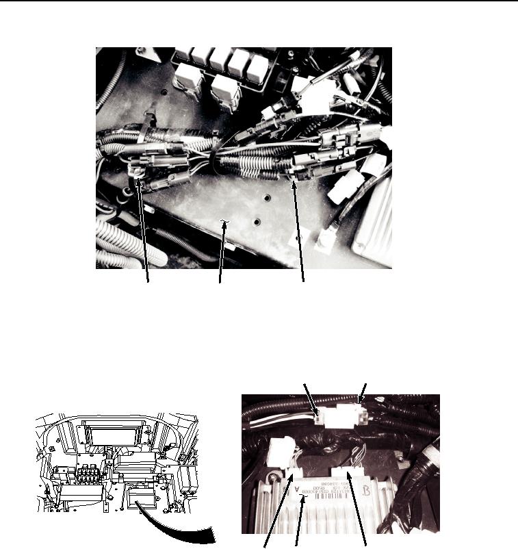
INSTALLATION - Continued
41, 42, 43
20
41, 42, 43
HYEX02600
Figure 31. Wiring Harness Clamps Installation.
7.
Connect cab wiring harness W1 at connection A8 (Figure 32, Item 39) to 12 volt power converter connector
(Figure 32, Item 40).
39
40
36
37
38
HYEX02599
Figure 32.
Connect Information Controller Wiring Harness.
8.
Connect cab wiring harness W1 at connection X34 (Figure 32, Item 38) to information controller (Figure 32,
Item 37).
9.
Connect cab wiring harness W1 at connection X32 (Figure 32, Item 36) to information controller (Figure 32,
Item 37).
10.
Connect cab wiring harness W1 at connection B26 (Figure 33, Item 34) to left speaker wiring (Figure 33, Item
35).