
TM 5-3805-294-23-4
0572
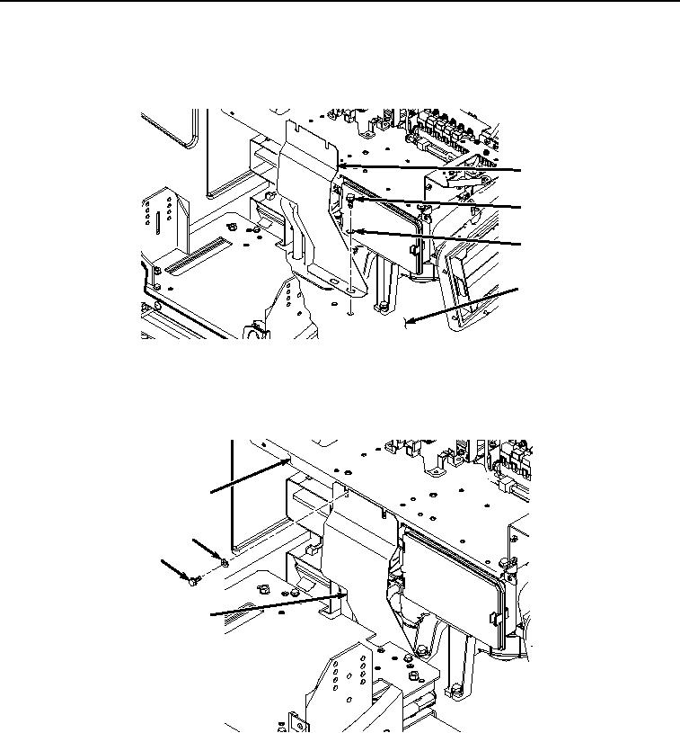
INSTALLATION - Continued
2.
Install support bracket (Figure 27, Item 54) to cab (Figure 27, Item 51) with two bolts (Figure 27, Item 55) and
washers (Figure 27, Item 56).
54
55
56
51
HYEX02604
Figure 27. Support Bracket Installation.
3.
Install bolt (Figure 28, Item 52) and washer (Figure 28, Item 53) to support bracket (Figure 28, Item 54) and
bracket (Figure 28, Item 20).
20
53
52
54
HYEX02603
Figure 28. Support Bracket Screw Installation.
4.
Install fuse box bracket (Figure 29, Item 50) to cab (Figure 29, Item 51) and bracket (Figure 29, Item 20) with
four bolts (Figure 29, Item 48) and washers (Figure 29, Item 49).