
TM 5-3805-294-23-4
0572
INSTALLATION - Continued
14
15
16
14
11
12
13
14
HYEX02595
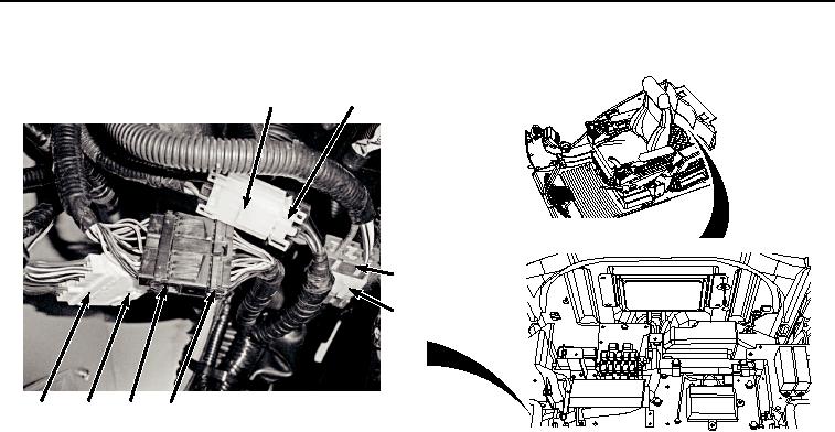
Figure 37. Connect Switch Panel Wiring Harness.
18.
Connect cab wiring harness W1 at connection X39 (Figure 37, Item 15) to right-hand console wiring harness
W11 (Figure 37, Item 14).
19.
Connect cab wiring harness W1 at connection X38 (Figure 37, Item 13) to right-hand console wiring harness
W11 (Figure 37, Item 14).
20.
Connect cab wiring harness W1 at connection X27 (Figure 37, Item 11) to switch panel A9 pigtail wiring harness
(Figure 37, Item 12).
21.
Connect cab wiring harness W1 at connection X24 (Figure 38, Item 10) to monitor controller wiring harness
W3 (Figure 38, Item 8).