
TM 5-3805-294-23-4
0572
INSTALLATION - Continued
7
9
10
8
HYEX02594
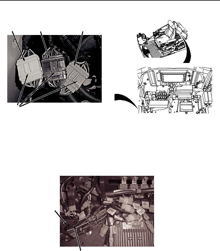
Figure 38. Connect Right Side Cab Wiring Harness.
22.
Connect cab wiring harness W1 at connection X23 (Figure 38, Item 9) to monitor controller wiring harness W3
(Figure 38, Item 8).
23.
Connect cab wiring harness W1 at connection X22 (Figure 38, Item 7) to monitor controller wiring harness W3
(Figure 38, Item 8).
24.
Connect wiring harness AUX 2/X62 (Figure 39, Item 5) to auxiliary wiring harness W13 connector AUX 2/X62
(Figure 39, Item 6).
5
6
HYEX02593
Figure 39.
Connect Auxiliary Wiring Harness.
25.
Connect wiring harnesses red wire (Figure 40, Item 3) to auxiliary fuse box wiring harness W13 red wire
connector AUX 3/X63 (Figure 40, Item 4).