
TM 5-3805-294-23-4
0572
REMOVAL
57, 58
51
20
HYEX02682
Figure 15.
Bracket Removal.
END OF TASK
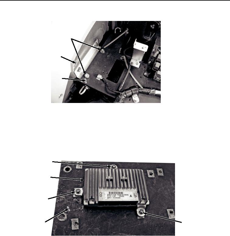
DISASSEMBLY
1.
Remove three screws (Figure 16, Item 59), lockwashers (Figure 16, Item 60), washers (Figure 16, Item 61),
and information controller (Figure 16, Item 37) from bracket (Figure 16, Item 20). Discard lockwashers.
59, 60, 61
37
59, 60, 61
59, 60, 61
20
HYEX02605
Figure 16. Information Controller Removal.
2.
Remove two screws (Figure 17, Item 62), lockwashers (Figure 17, Item 63), washers (Figure 17, Item 64), and
bracket (Figure 17, Item 65) from bracket (Figure 17, Item 20). Discard lockwashers.