
TM 5-3805-294-23-4
0572
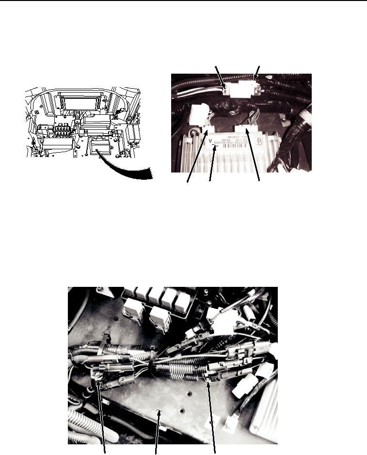
REMOVAL - Continued
19.
Disconnect cab wiring harness W1 at connection X32 (Figure 9, Item 36) from information controller (Figure
9, Item 37).
39
40
36
37
38
HYEX02599
Figure 9. Information Controller Wiring Harness Disconnect.
20.
Disconnect cab wiring harness W1 at connection X34 (Figure 9, Item 38) from information controller (Figure
9, Item 37).
21.
Disconnect cab wiring harness W1 at connection A8 (Figure 9, Item 39) from 12 volt power converter connector
(Figure 9, Item 40).
22.
Remove two bolts (Figure 10, Item 41), washers (Figure 10, Item 42), and clamps (Figure 10, Item 43) from
bracket (Figure 10, Item 20).
41, 42, 43
20
41, 42, 43
HYEX02600
Figure 10. Wiring Harness Clamps Removal.