
TM 5-3805-294-23-4
0572
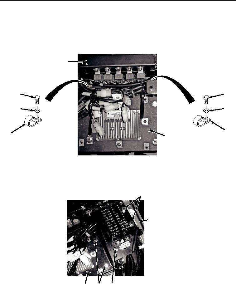
REMOVAL - Continued
NOTE
Move wiring harness as required to access screws, washers, and clamps.
23.
Remove two bolts (Figure 11, Item 44), washers (Figure 11, Item 45), clamps (Figure 11, Item 46), and relay
bracket (Figure 11, Item 47) from bracket (Figure 11, Item 20).
47
44
44
45
45
46
46
20
HYEX02601
Figure 11.
Relay Bracket Removal.
24.
Remove four bolts (Figure 12, Item 48) and washers (Figure 12, Item 49) from bracket (Figure 12, Item 20),
fuse box bracket (Figure 12, Item 50), and cab (Figure 12, Item 51).
48, 49
51
20
48, 49 50
HYEX02602
Figure 12.
Fuse Box Bracket Removal.