
TM 5-3805-294-23-4
0583
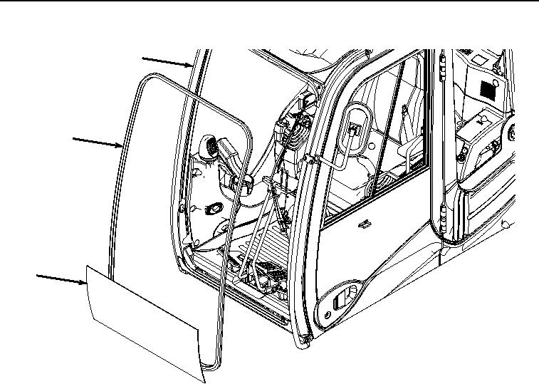
WINDSHIELD ISOLATOR REMOVAL - Continued
10
12
11
HYEX02774
Figure 3.
Windshield Isolator Removal.
2.
Remove windshield isolator (Figure 3, Item 12) from operator cab (Figure 3, Item 10).
3.
Clean mating surface of operator cab (Figure 3, Item 10).
END OF TASK
WINDSHIELD DISASSEMBLY
1.
Remove four bolts (Figure 4, Item 13) and lock handle (Figure 4, Item 14) from windshield assembly (Figure
4, Item 3). Discard bolts.