
TM 5-3805-294-23-4
0583
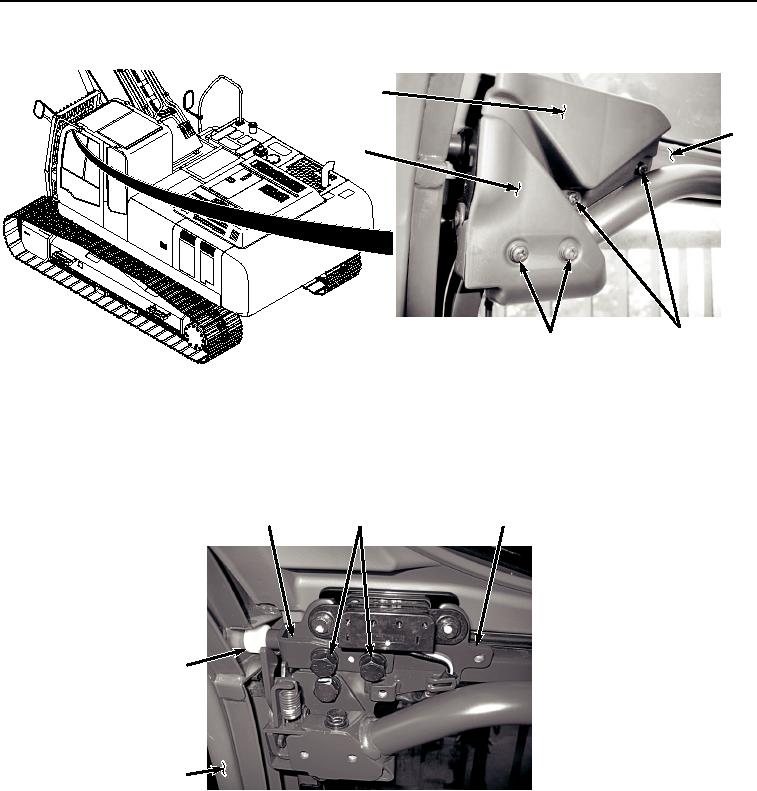
WINDSHIELD ASSEMBLY REMOVAL - Continued
2
3
5
1
4
HYEX02773
Figure 1.
Windshield Assembly Covers Removal.
2.
Remove four screws (Figure 1, Item 4) and two covers (Figure 1, Item 5) from windshield assembly (Figure 1,
Item 3). Discard screws.
3.
Remove four bolts (Figure 2, Item 6), washers (Figure 2, Item 7), two brackets (Figure 2, Item 8), and rollers
(Figure 2, Item 9) from windshield assembly (Figure 2, Item 3).
8
6, 7
3
9
10
HYEX02905
Figure 2.
Windshield Assembly Brackets Removal.
4.
With the aid of an assistant, remove windshield assembly (Figure 2, Item 3) from operator cab (Figure 2, Item
10).
END OF TASK
WINDSHIELD ISOLATOR REMOVAL
1.
Remove front windowpane (Figure 3, Item 11) from operator cab (Figure 3, Item 10).