
TM 5-3805-294-23-4
0583
WINDSHIELD DISASSEMBLY - Continued
28
29
3
27
HYEX02780
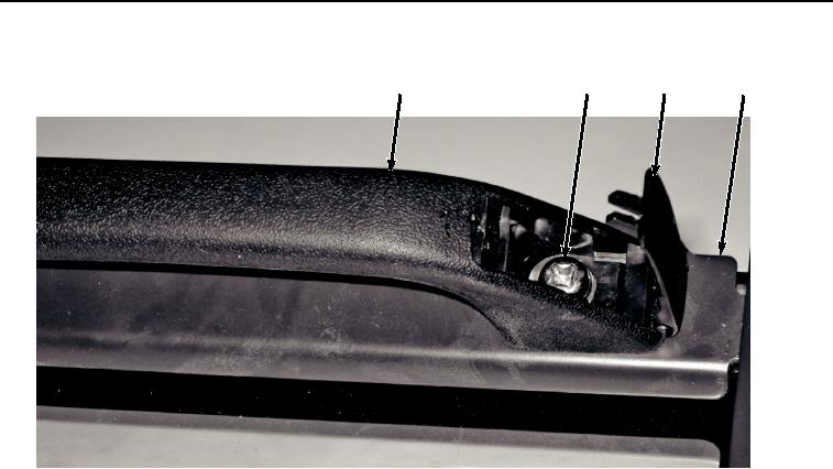
Figure 7.
Handle Removal.
10.
Remove two screws (Figure 7, Item 29) and handle (Figure 7, Item 28) from windshield assembly (Figure 7,
Item 3). Discard screws.
END OF TASK
WINDSHIELD ASSEMBLY
1.
Install handle (Figure 8, Item 28) to windshield assembly (Figure 8, Item 3) with two screws (Figure 8, Item
29).