
TM 5-3805-294-23-4
0598
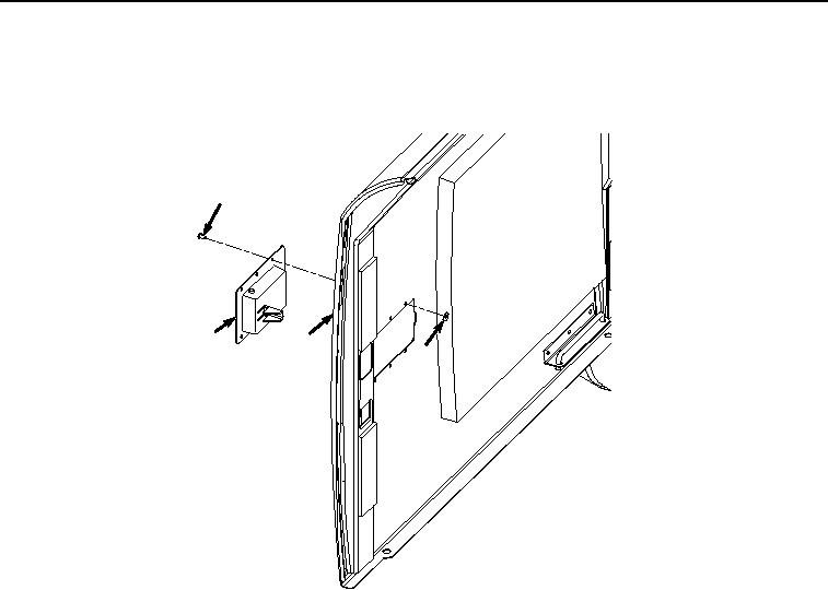
LATCH INSTALLATION
1.
Install latch (Figure 4, Item 9) to door (Figure 4, Item 4).
7
9
4
8
HYEX01033
Figure 4. Latch Installation.
2.
Install six washers (Figure 4, Item 8) and rivets (Figure 4, Item 7) to latch (Figure 4, Item 9) and door (Figure
4, Item 4).
END OF TASK
ISOLATOR REMOVAL
NOTE
Note isolator layout on door prior to removal to ensure proper installation.
1.
Remove isolator (Figure 5, Item 10) from door (Figure 5, Item 4).