
TM 5-3805-294-23-4
0597
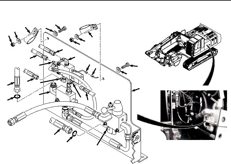
INSTALLATION - Continued
1
2
3
3
4
2
3
4
12
13
14
20
21
15
1
3
16
17
9
5
10
19
11
18
6
8
7
HYEX02226
Figure 4. Valve Mount Plate Installation.
4.
Connect connector (Figure 4, Item 21) to connector (Figure 4, Item 20).
5.
Install hose (Figure 4, Item 18) to fitting (Figure 4, Item 19).
6.
Install hose (Figure 4, Item 16) to fitting (Figure 4, Item 17).
7.
Install hose (Figure 4, Item 14) to fitting (Figure 4, Item 15).
8.
Install hose (Figure 4, Item 12) to fitting (Figure 4, Item 13).
9.
Lightly lubricate O-ring (Figure 4, Item 11) with clean oil.
10.
Install O-ring (Figure 4, Item 11) to fitting (Figure 4, Item 10).
11.
Install hose (Figure 4, Item 9) to fitting (Figure 4, Item 10).
12.
Lightly lubricate O-ring (Figure 4, Item 8) with clean oil.
13.
Install O-ring (Figure 4, Item 8) to fitting (Figure 4, Item 7).
14.
Install hose (Figure 4, Item 6) to fitting (Figure 4, Item 7).
15.
Install two bolts (Figure 4, Item 1), clamps (Figure 4, Item 2), four washers (Figure 4, Item 3), and locknuts
(Figure 4, Item 4) to valve mount plate (Figure 4, Item 5).
END OF TASK