
TM 5-3805-294-23-4
0598
DOOR INSTALLATION - Continued
2.
With the aid of an assistant, position and align door (Figure 2, Item 4) to hydraulic pump compartment rear
vertical cover (Figure 2, Item 5).
3.
With the aid of an assistant, install door (Figure 2, Item 4) to hydraulic pump compartment rear vertical cover
(Figure 2, Item 5) with four washers (Figure 2, Item 3), lockwashers (Figure 2, Item 2), and nuts (Figure 2, Item
1).
END OF TASK
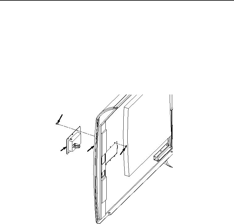
LATCH REMOVAL
1.
Remove six rivets (Figure 3, Item 7) and washers (Figure 3, Item 8) from latch (Figure 3, Item 9) and door
(Figure 3, Item 4). Discard rivets.
7
9
4
8
HYEX01033
Figure 3. Latch Removal.
2.
Remove latch (Figure 3, Item 9) from door (Figure 3, Item 4).
END OF TASK