
TM 5-3805-294-23-4
0598
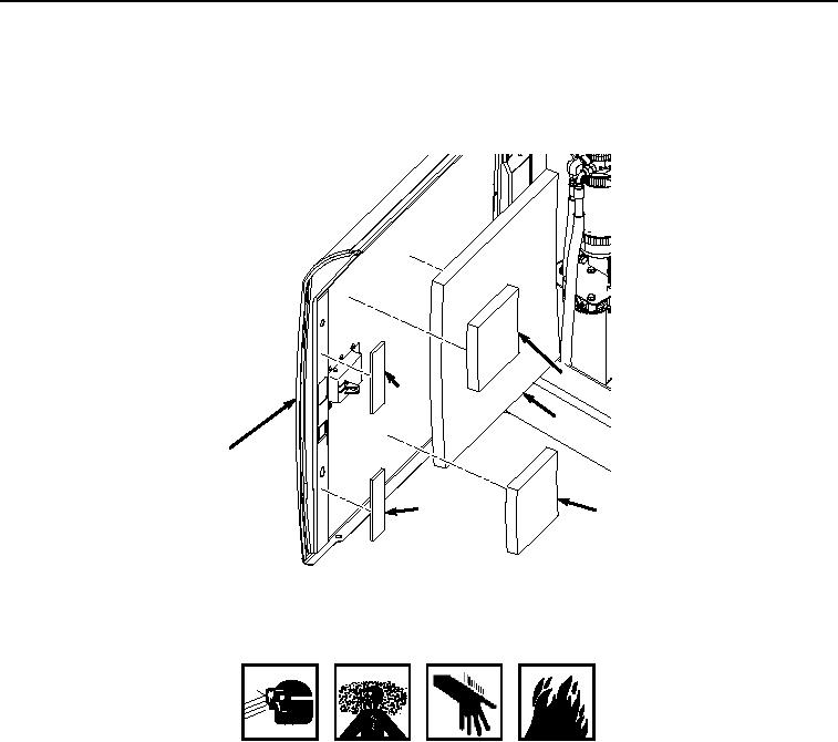
ISOLATOR INSTALLATION
1.
Layout and arrange two isolators (Figure 6, Item 12), two isolators (Figure 6, Item 11), and isolator (Figure 6,
Item 10) on door (Figure 6, Item 4) for placement prior to installing with adhesive.
11
12
10
4
12
11
HYEX01034
Figure 6.
Isolator Installation.
WARNING
ADHESIVES AND SEALANTS
2.
Apply adhesive to the back sides of two isolators (Figure 6, Item 12).
3.
Apply two isolators (Figure 6, Item 12) to door (Figure 6, Item 4) and apply pressure.
4.
Apply adhesive to the back side of two isolators (Figure 6, Item 11).
5.
Apply two isolators (Figure 6, Item 11) to door (Figure 6, Item 4) and apply pressure.
6.
Apply adhesive to the back side of isolator (Figure 6, Item 10).
7.
Apply isolator (Figure 6, Item 10) to door (Figure 6, Item 4) and apply pressure.
END OF TASK