
TM 5-3805-294-23-4
0614
INSTALLATION - Continued
2
1
4
5
3
HYEX01779
Figure 4. Proximity Sensor Installation.
3.
Install jam nut (Figure 4, Item 3) to sensor (Figure 4, Item 4).
4.
Connect electrical connector (Figure 4, Item 1) to wiring harness (Figure 4, Item 2).
END OF TASK
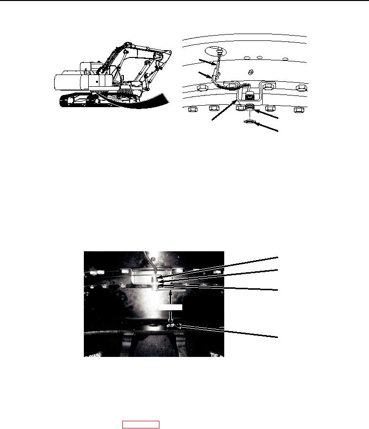
ADJUSTMENT
Adjust jam nuts (Figure 5, Item 3) and (Figure 5, Item 6) as necessary to obtain a 6.5 in. clearance between
sensor (Figure 5, Item 4) and top surface of machine frame (Figure 5, Item 7).
4
6
3
6.50 IN
7
HYEX01785
Figure 5.
Proximity Sensor Adjustment.
END OF TASK
FOLLOW-ON MAINTENANCE
1.
Connect negative battery cable. (WP 0521)
2.
Perform the Standard Follow-On Maintenance Instructions. (Volume 3, WP 0384)
END OF TASK
END OF WORK PACKAGE