
TM 5-3805-294-23-4
0615
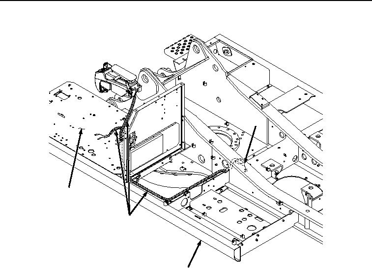
REMOVAL
23
24
23
25
HYEX02194
Figure 6.
Wiring Harness Routing and Removal.
END OF TASK
INSTALLATION
1.
Attach twine to red wire terminal (Figure 7, Item 3), black wire terminal (Figure 7, Item 7), red wire (Figure 7,
Item 8), and red wire (Figure 7, Item 10) and pull wiring harness (Figure 7, Item 23) along original route through
machine (Figure 7, Item 25) back up into cab (Figure 7, Item 24) as noted prior to removal.