
TM 5-3805-294-23-4
0615
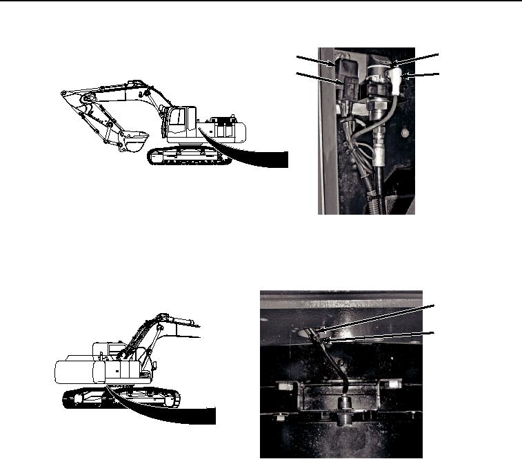
INSTALLATION - Continued
17
15
14
16
HYEX02192
Figure 9. Wiring Harness To Relay and Pressure Switch Installation.
4.
Connect wiring harness connector (Figure 9, Item 14) to relay (Figure 9, Item 15).
5.
Connect wiring harness (Figure 10, Item 12) to proximity sensor electrical connector (Figure 10, Item 13).
12
13
HYEX02190
Figure 10.
Wiring Harness To Proximity Sensor Installation.
6.
Connect wiring harness red wire (Figure 11, Item 10) to auxiliary fuse box wiring harness W13 red wire
connector AUX 3/X63 (Figure 11, Item 11).