
TM 5-3805-294-23-4
0615
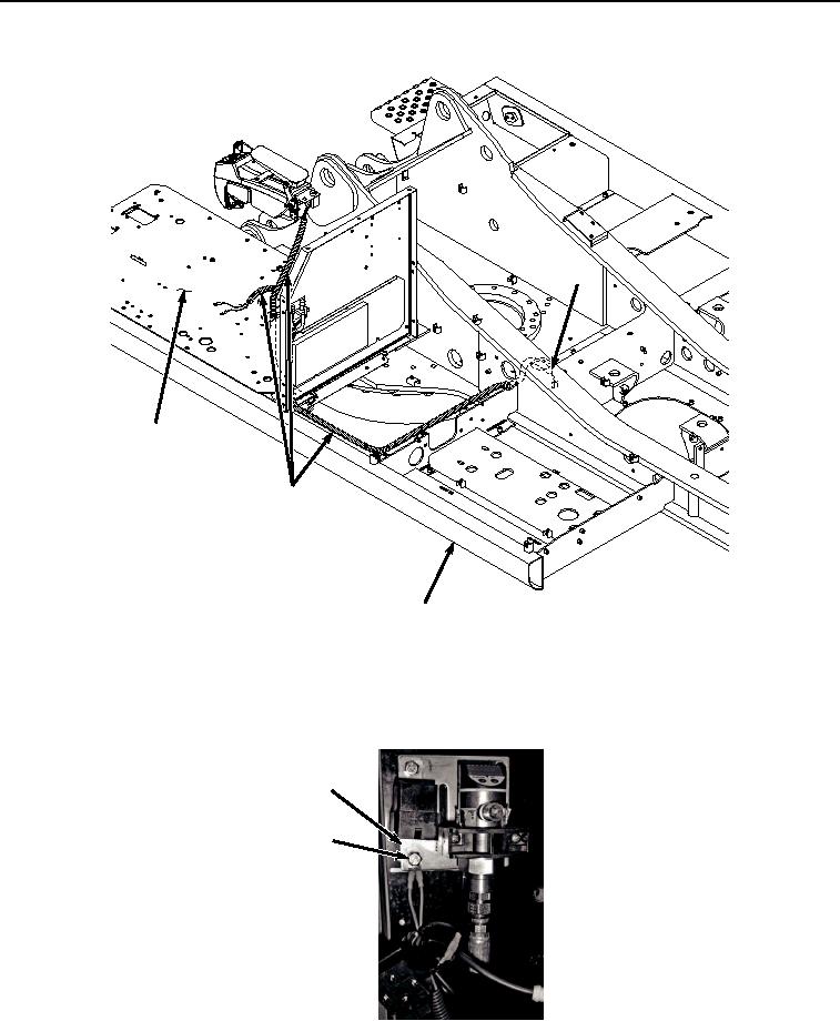
INSTALLATION - Continued
23
24
23
25
HYEX02194
Figure 7. Wiring Harness Routing and Installation.
2.
Install two wire terminals (Figure 8, Item 19) and (Figure 8, Item 20) to storage compartment cover (Figure 8,
Item 22) with bolt (Figure 8, Item 18) and locknut (Figure 8, Item 21).
22
18, 19, 20, 21
HYEX02193
Figure 8.
Ground To Storage Compartment Cover Installation.
3.
Connect wiring harness connector (Figure 9, Item 16) to pressure switch (Figure 9, Item 17).