
TM 5-3805-294-23-4
0615
REMOVAL - Continued
9
8
11
10
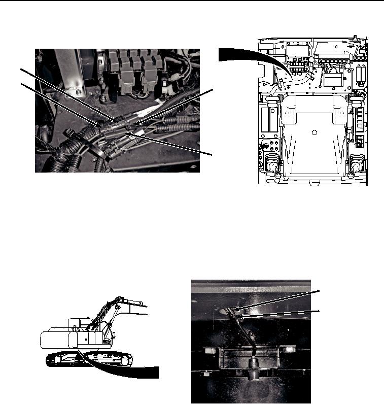
HYEX02188
Figure 2.
Wiring Harness From Auxiliary Fuse Box Wiring Harness W13 Removal.
4.
Disconnect wiring harnesses red wire (Figure 2, Item 10) from auxiliary fuse box wiring harness W13 red wire
connector AUX 3/X63 (Figure 2, Item 11).
5.
Pull red and black wire terminals and red and black wires together and attach twine to aid in installation.
6.
Disconnect wiring harness (Figure 3, Item 12) from proximity sensor electrical connector (Figure 3, Item 13).
12
13
HYEX02190
Figure 3. Wiring Harness From Proximity Sensor Removal.
7.
Disconnect wiring harness connector (Figure 4, Item 14) from relay (Figure 4, Item 15).