
TM 5-3805-294-23-4
0633
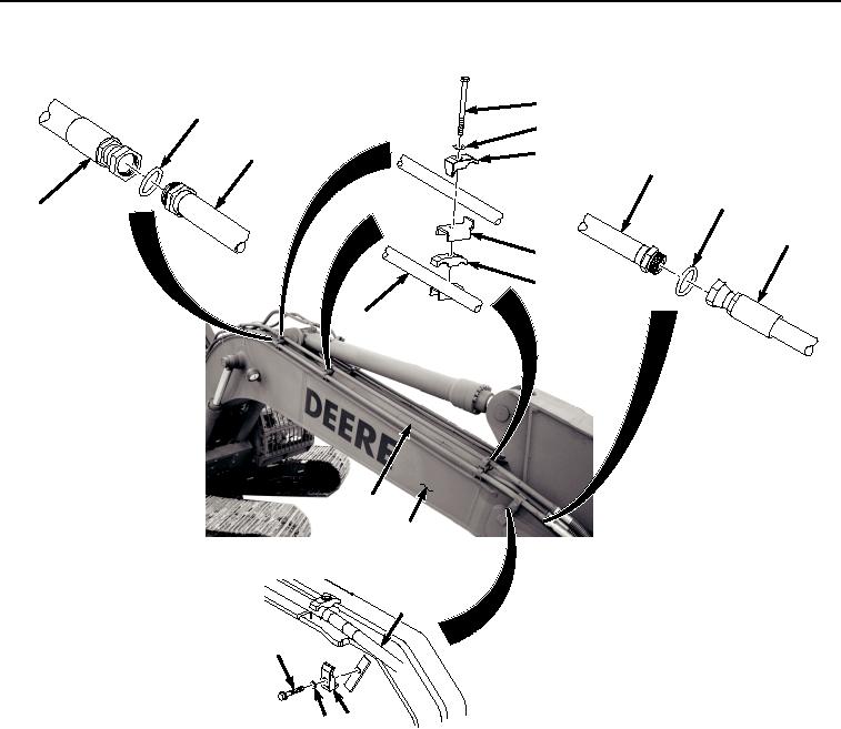
RIGHT SIDE UPPER LINE REMOVAL - Continued
50
44
51
43
52
43
46
36
45
53
54
43
43
20
43
47
HYEX01753
48 49
Figure 4. Right Side Upper Line Removal.
2.
Remove O-ring (Figure 4, Item 44) from line (Figure 4, Item 43). Discard O-ring.
3.
Remove hose (Figure 4, Item 45) from line (Figure 4, Item 43).
4.
Remove O-ring (Figure 4, Item 46) from line (Figure 4, Item 43). Discard O-ring.
5.
Remove screw (Figure 4, Item 47), washer (Figure 4, Item 48), and clamp (Figure 4, Item 49) from line (Figure
4, Item 43).
6.
Remove three bolts (Figure 4, Item 50), washers (Figure 4, Item 51), clamps (Figure 4, Item 52), flanges (Figure
4, Item 53), and clamps (Figure 4, Item 54) from line (Figure 4, Item 43).
7.
Remove line (Figure 4, Item 43) from boom (Figure 4, Item 20).
END OF TASK