
TM 5-3805-294-23-4
0633
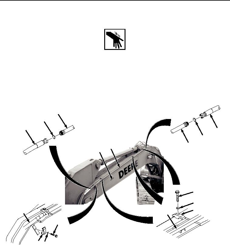
LEFT SIDE UPPER LINE INSTALLATION
WARNING
NOTE
Install hoses and position fittings as noted prior to removal.
Install clamps as noted prior to removal.
1.
Install line (Figure 7, Item 21) to boom (Figure 7, Item 20) with three bolts (Figure 7, Item 28), washers (Figure
7, Item 29), and clamps (Figure 7, Item 30).
21
24
23
15
22
21
21
20
28
29
30
21
21
25
HYEX01751
27 26
Figure 7. Left Side Upper Line Installation.
2.
Install clamp (Figure 7, Item 27) to line (Figure 7, Item 21) with bolt (Figure 7, Item 25) and washer (Figure 7,
Item 26).
3.
Lightly lubricate O-ring (Figure 7, Item 24) with clean oil.
4.
Install O-ring (Figure 7, Item 24) to line (Figure 7, Item 21).
5.
Install hose (Figure 7, Item 23) to line (Figure 7, Item 21).
6.
Lightly lubricate O-ring (Figure 7, Item 22) with clean oil.