
TM 5-3805-294-23-4
0633
LEFT SIDE UPPER LINE INSTALLATION - Continued
7.
Install O-ring (Figure 7, Item 22) to line (Figure 7, Item 21).
8.
Install hose (Figure 7, Item 15) to line (Figure 7, Item 21).
END OF TASK
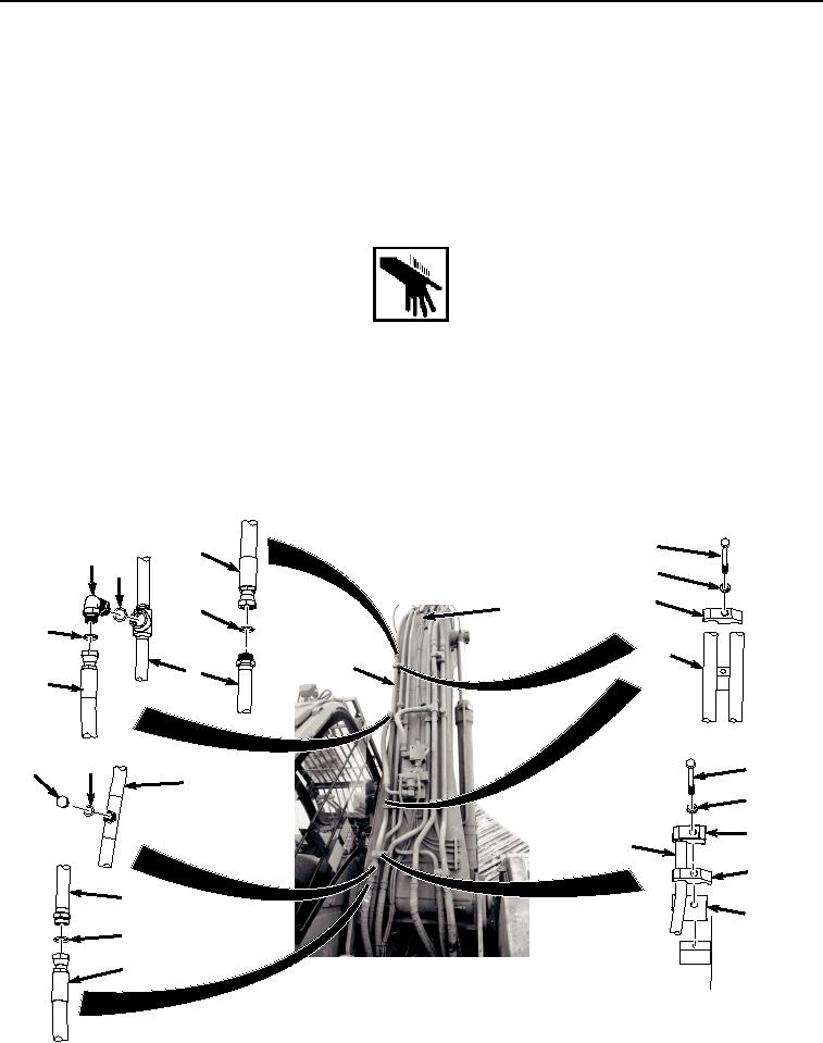
LEFT SIDE LOWER LINE INSTALLATION
WARNING
NOTE
Install hoses and position fittings as noted prior to removal.
Install clamps as noted prior to removal.
1.
Install line (Figure 8, Item 2) to boom (Figure 8, Item 20) with two bolts (Figure 8, Item 17), washers (Figure 8,
Item 18), and clamps (Figure 8, Item 19).
17
15
12
13
18
19
16
20
14
2
2
2
11
5
6
4
2
7
8
2
9
2
10
3
1
HYEX01750
Figure 8. Left Side Lower Line Installation.