
TM 5-3805-294-23-4
0655
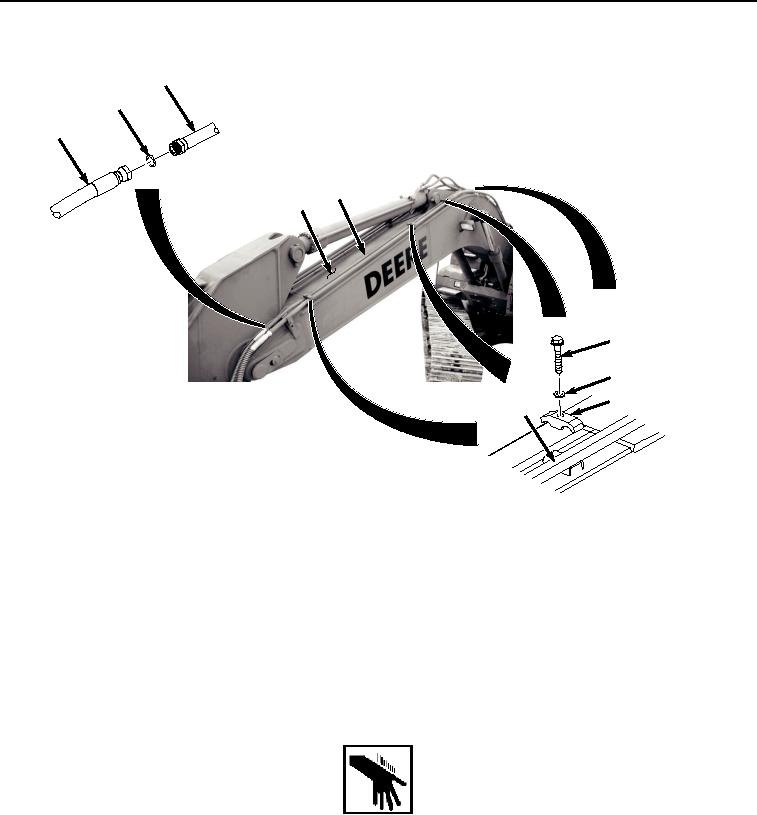
LEFT SIDE UPPER LINE REMOVAL - Continued
20
26
25
20
9
27
28
29
20
HYEX01771
Figure 4.
Left Side Upper Line Removal.
2.
Remove O-ring (Figure 4, Item 26) from line (Figure 4, Item 20). Discard O-ring.
3.
Remove four bolts (Figure 4, Item 27), washers (Figure 4, Item 28), and clamps (Figure 4, Item 29) from line
(Figure 4, Item 20).
4.
Remove line (Figure 4, Item 20) from boom (Figure 4, Item 9).
END OF TASK
LEFT SIDE UPPER LINE INSTALLATION
WARNING
NOTE
Install hoses and fittings as noted during removal.
Install clamps as noted during removal.
Install tie wraps as noted during removal.
1.
Install line (Figure 5, Item 20) to boom (Figure 5, Item 9) with four bolts (Figure 5, Item 27), washers (Figure
5, Item 28), and clamps (Figure 5, Item 29).