
TM 5-3805-294-23-4
0655
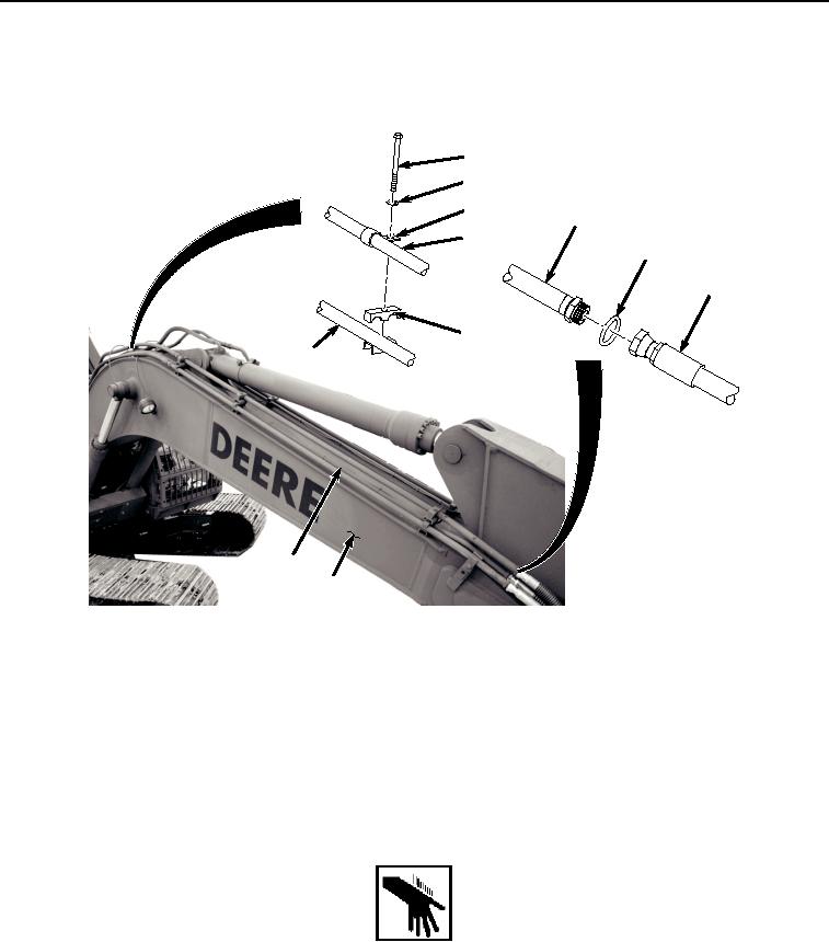
RIGHT SIDE UPPER LINE INSTALLATION - Continued
1.
Install line (Figure 7, Item 4) to boom (Figure 7, Item 9) with bolt (Figure 7, Item 12), washer (Figure 7, Item
13), hose clamp (Figure 7, Item 14), hose (Figure 7, Item 15), and clamp (Figure 7, Item 16).
12
13
14
4
15
11
10
16
4
4
9
HYEX01769
Figure 7.
Right Sided Upper Line Installation.
2.
Lightly lubricate O-ring (Figure 7, Item 11) with clean oil.
3.
Install O-ring (Figure 7, Item 11) to line (Figure 7, Item 4).
4.
Install hose (Figure 7, Item 10) to line (Figure 7, Item 4).
END OF TASK
RIGHT SIDE LOWER LINE INSTALLATION
WARNING
NOTE
Install hoses and fittings as noted during removal.
Install clamps as noted during removal.