
TM 5-3805-294-23-4
0656
REMOVAL - Continued
WARNING
Do not remove pin from right side of bucket link and arm link. Bucket link and arm link can
come free and fall. Failure to comply may result in injury or death to personnel.
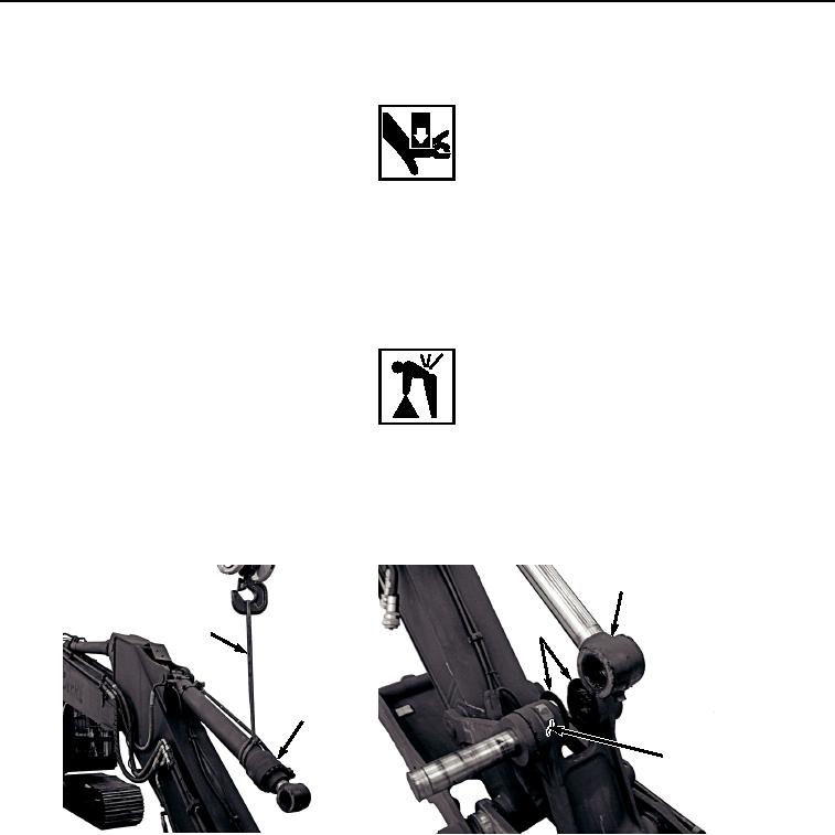
5.
Move pin (Figure 3, Item 6) just enough to free left side of bucket link (Figure 3, Item 8) and bucket cylinder
(Figure 3, Item 2), leaving pin (Figure 3, Item 6) installed in right side of bucket link (Figure 3, Item 8) and arm
link (Figure 3, Item 9).
WARNING
Bucket cylinder weighs 430 lb (195 kg). Do not attempt to lift or move bucket cylinder without
the aid of an assistant and suitable lifting device. Failure to comply may result in injury or
death to personnel.
6.
With the aid of an assistant and suitable lifting device (Figure 4, Item 1), raise bucket cylinder (Figure 4, Item
2) from bucket link (Figure 4, Item 8) to allow for removal of two shims (Figure 4, Item 10).
2
10
1
2
8
HYEX02712
Figure 4.
Raise Bucket Cylinder.
7.
Remove two shims (Figure 4, Item 10) from between bucket cylinder (Figure 4, Item 2) and bucket link (Figure
4, Item 8).
8.
Start engine (TM 5-3805-294-10).
9.
Fully retract bucket cylinder (Figure 4, Item 2).
10.
Shut down engine (TM 5-3805-294-10).
11.
Relieve hydraulic system pressure. (Volume 5, WP 0767)
12.
Remove hose (Figure 5, Item 11) from fitting (Figure 5, Item 12).