
TM 5-3805-294-23-4
0656
REMOVAL - Continued
24.
Remove O-ring (Figure 12, Item 30) from fitting (Figure 12, Item 20). Discard O-ring.
25.
Remove bolt (Figure 12, Item 32), lockwasher (Figure 12, Item 33), and clamp (Figure 12, Item 34) from band
(Figure 12, Item 35). Discard lockwasher.
26.
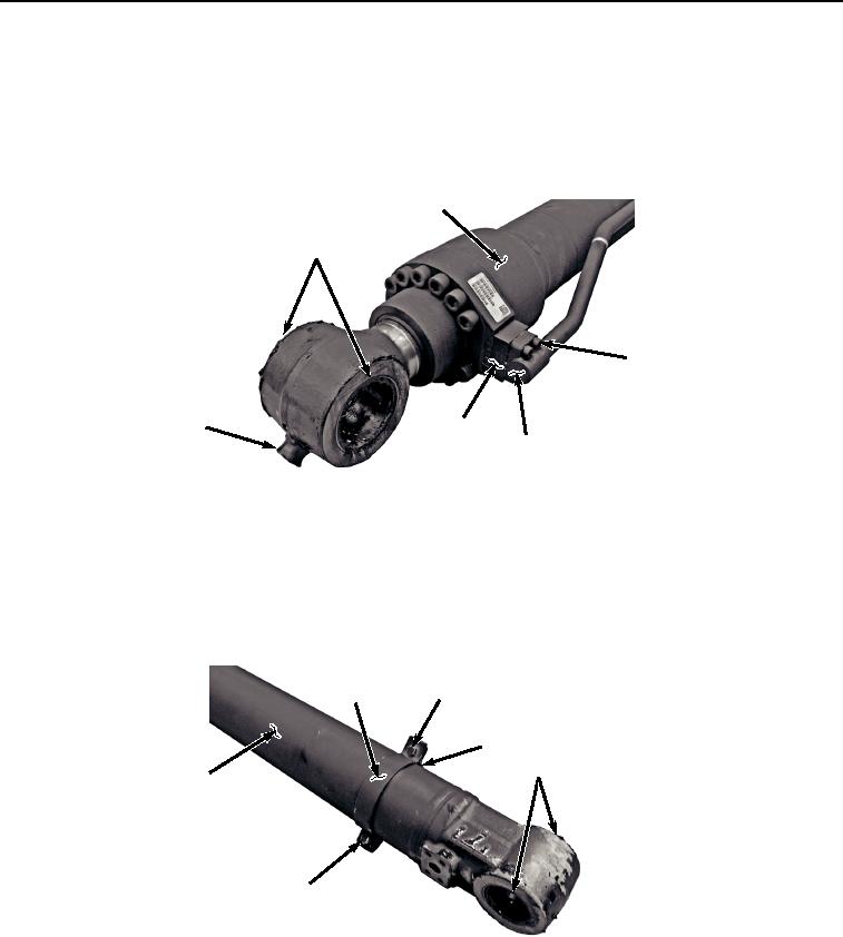
Remove grease fitting (Figure 13, Item 36) from bucket cylinder (Figure 13, Item 2).
2
41
37
36
39, 40
31, 38
HYEX02721
Figure 13.
Lower Adapter Removal.
27.
Remove four screws (Figure 13, Item 37), line (Figure 13, Item 31), O-ring (Figure 13, Item 38), adapter (Figure
13, Item 39), and O-ring (Figure 13, Item 40) from bucket cylinder (Figure 13, Item 2). Discard O-rings.
28.
Remove two seals (Figure 13, Item 41) from bucket cylinder (Figure 13, Item 2). Discard seals.
29.
Remove two bolts (Figure 14, Item 42), lockwashers (Figure 14, Item 43), clamp (Figure 14, Item 44), and band
(Figure 14, Item 45) from bucket cylinder (Figure 14, Item 2). Discard lockwashers.
42, 43
44
45
46
2
42, 43
HYEX02722
Figure 14.
Clamp and Band Removal.
30.
Remove two seals (Figure 14, Item 46) from bucket cylinder (Figure 14, Item 2). Discard seals.
31.
Remove fitting (Figure 15, Item 12) and O-ring (Figure 15, Item 47) from adapter (Figure 15, Item 17).