
TM 5-3805-294-23-4
0656
REMOVAL - Continued
12
11
HYEX02713
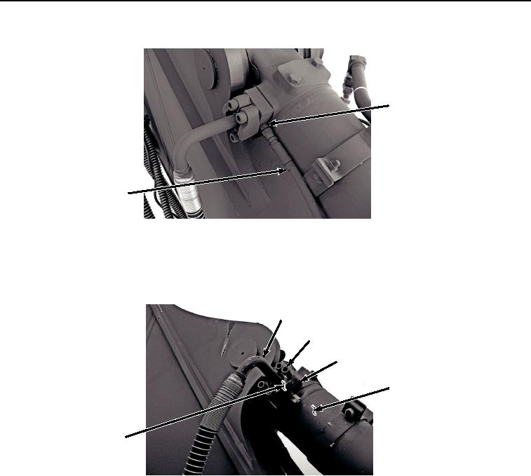
Figure 5.
Upper Right Hose Removal.
13.
Remove four screws (Figure 6, Item 13), two clamp halves (Figure 6, Item 14), hose (Figure 6, Item 15), O-
ring (Figure 6, Item 16), adapter (Figure 6, Item 17), and O-ring (Figure 6, Item 18) from bucket cylinder (Figure
6, Item 2). Discard O-rings.
15, 16
13
17, 18
2
14
HYEX02714
Figure 6. Hose and Clamp Halves Removal.
14.
Remove hose (Figure 7, Item 19) from fitting (Figure 7, Item 20).