
TM 5-3805-294-23-4
0655
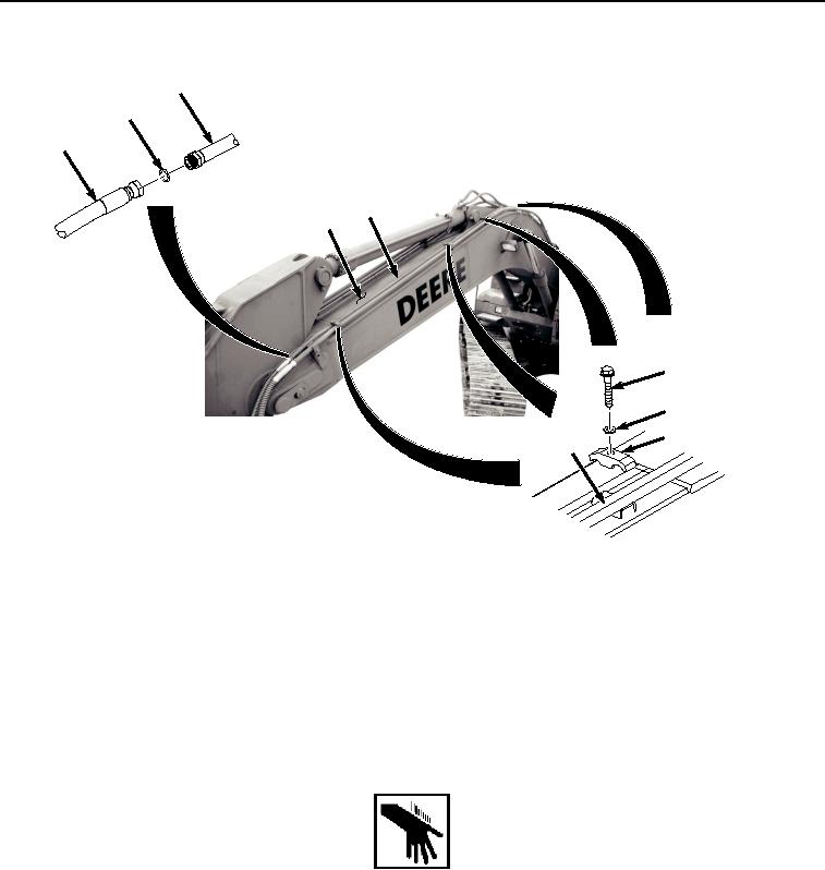
LEFT SIDE UPPER LINE INSTALLATION - Continued
20
26
25
20
9
27
28
29
20
HYEX01771
Figure 5. Left Side Upper Line Installation.
2.
Lightly lubricate O-ring (Figure 5, Item 26) with clean oil.
3.
Install O-ring (Figure 5, Item 26) to line (Figure 5, Item 20).
4.
Install hose (Figure 5, Item 25) to line (Figure 5, Item 20).
END OF TASK
LEFT SIDE LOWER LINE INSTALLATION
WARNING
NOTE
Install hoses and fittings as noted during removal.
Install clamps as noted during removal.
1.
Install line (Figure 6, Item 18) to boom (Figure 6, Item 9) with bolt (Figure 6, Item 22), washer (Figure 6, Item
23), and clamp (Figure 6, Item 24).